
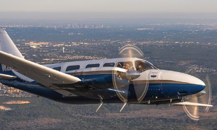
The inspiration for writing this tutorial came from a fatal accident that occurred on April 22, 2022 at Burley, Idaho KBYI. The pilot of a Cessna 208B Caravan flew the RNAV RWY 20 in IMC where there was no published glidepath, failed to meet the crossing restriction of a stepdown fix, and collided with an obstacle below MDA.
While the NTSB has yet to assign a cause for the accident, it is my belief that the pilot inappropriately flew the V+ reference glidepath below MDA in IMC resulting in the collision with the obstacle.
NOTE: I recommend that the reader access all pertinent charts on their iPad and follow the lesson from there.
Editor’s Note: While we rarely wish to discuss any accident before the final publication of the NTSB report, we felt as the author does, that there was a greater risk to pilots in not explaining what may have happened in the hopes that this story may prevent another tragic outcome.
INTRODUCTION
When WAAS is available, most general aviation navigation systems will provide the pilot with a reference glidepath based on a 3-degree descent angle. The name of the reference glidepath varies with the navigator installed. For example, on the Pilatus PC- 12NG I fly professionally, it’s simply called the Vertical Glidepath, or VGP. On some Garmin systems, it is referred to as V+, and on the G1000 and Avidyne 540, it is referred to as LNAV+V, or Advisory Vertical Guidance. To keep it simple, I will refer to it as a “reference glidepath,” since reference is its intended use.
NOTE: The reference glidepath should not be confused with the LPV or VNAV function associated with an LPV or LNAV/ VNAV approach. If flown correctly, the LPV and VNAV glidepaths on these approaches guarantee obstacle clearance, but only down to the published minimums.
It is imperative that pilots understand the limitations of using the reference glidepath on instrument approaches in IMC and/ or VFR at night where there is no published vertical guidance. Keep in mind that reference glidepaths do not guarantee obstacle clearance, nor do they compensate for displaced thresholds. In addition, your autopilot will not track a reference glidepath as it may on an LPV or VNAV path.
A secondary goal of this tutorial is to encourage pilots to study their approach charts with a critical eye based on the forecast surface winds before takeoff. This is the only way to see the small but critically important details, such as those discussed here, without the distraction of flying the airplane.
WHAT THE REFERENCE GLIDEPATH DOES
- Provides a constant 3-degree descent angle when approaching the airport or runway selected in the navigator. This relieves the pilot of having to calculate where to start down when flying VFR, especially at night or on down wind or base leg in the pattern.
- It can be used on LNAV, Localizer, or LP approaches where there is no published glidepath to allow for a stabilized descent to MDA while observing the cautions mentioned below.
- In day VFR conditions, the reference glidepath can be used for a stabilized approach to a runway where a VASI, PAPI, LPV, VNAV, or an ILS glideslope is not available.
WHAT THE REFERENCE GLIDEPATH DOES NOT DO
- The reference glidepath will not provide for obstacle clearance, especially on an IFR approach or a visual approach at night.
- If followed on approaches that, due to obstacles, have descent angles greater than 3-degrees, it will result in being below the proper approach angle. Because of this, the reference glidepath does not guarantee that crossing fix altitudes will be met, or that obstacles will be cleared.
- It does not compensate for displaced thresholds. Following the reference glidepath to a runway with a significantly displaced threshold will result in an approach angle that is too low.
RED FLAGS FOR THE PRESENCE OF OBSTACLES
Before we fly an IFR approach in IMC or a VFR approach at night using a reference glidepath, it is imperative that we check the approach chart, airport diagram, and, if you are not instrument rated, the AFD for “red flags” which indicate that obstacles may be present in the final segment. We must also determine if the approach angle is greater than 3-degrees.
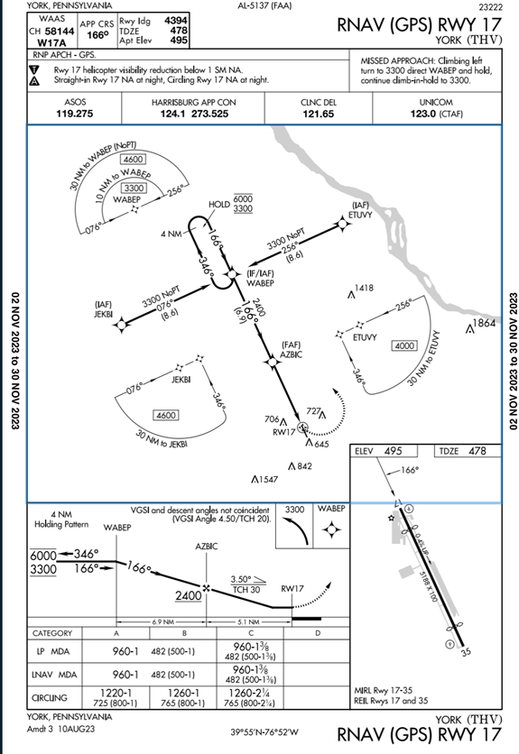
Look at the approach chart, airport diagram, and the AFD above for the RNAV(GPS) RWY 17 approach to York, Pennsylvania, KTHV. See if you can spot at least 4 red flags that indicate the presence of obstacles between the FAF and the threshold on this approach, or an approach angle greater than 3-degrees.
The four red flags that indicate obstacles are in the final approach path, or that the approach angle is greater than 3-degrees are as follows:
- Above the vertical profile it says “VGSI and descent angle not coincident (VGSI Angle 4.50/TCH 20).” This means that a descent angle of at least 4.5 degrees is required from the MDA to the displaced threshold to avoid close in obstacles. It also means that the Visual Glide Slope Indicator (PAPI), for this approach is greater than a normal 3-degree descent angle.
- The lack of a published glidepath such as an LPV or a VNAV approach path.
- The displaced threshold on Runway 17 as shown on the approach chart inset. The reason for a displaced threshold is that one or more obstacles penetrate the normal descent path. To compensate for this, the threshold is displaced down the runway to a point that allows for a more normal approach angle. Flying the reference glidepath to a runway with a displaced threshold will result in flying below the approach angle required to clear obstacles. Keep in mind that the reference glidepath is based on a 3-degree angle to the actual runway threshold, and not the displaced threshold.
NOTE: Pilots should always associate the presence of a displaced threshold with obstacles in the approach or departure path! - The note at the top of the approach chart that says “Straight-in and circling to RWY 17 NA at night.” This is a red flag that unlighted obstacles exist in the final approach segment that cannot be seen at night. In the AFD, it restates the note on the approach chart saying “GA 4.5 degrees, TCH 20 feet.” A Glidepath Angle of 4.5 degrees to achieve a Threshold Crossing Height of 20 (feet).” Flying the 3-degree reference glidepath will result in an approach angle that is well below 4.5 degrees. Flying the reference glidepath on the RNAV RWY 17 will put you well below the proper approach angle of 4.5 degrees. Following IFR in low visibility conditions or VFR at night, below MDA, may result in a controlled flight into the terrain, or CFIT type of accident. A PAPI is available for this runway and its use for descent below MDA is mandatory, even in day VFR conditions.
Have a website login already? Log in and start reading now.
Never created a website login before? Find your Customer Number (it’s on your mailing label) and register here.
JOIN HERE
Still have questions? Contact us here.
