
By Dr. Robert Tingley
Piper Owners Society Member, Seneca38173
Raymond L. Meisenheimer was completely unknown to me until recently, but he is, nonetheless, someone all of us in general aviation owe a great deal of gratitude.
The story begins back in January, when I picked my plane up from its annual inspection. During the short flight to my home field, I observed the ammeters dancing back and forth. I wasn’t terribly alarmed by this behavior. OEM panel meters are notoriously unreliable, especially in “experienced” airplanes like mine. And as I’d seen them dance before, only to settle down before we could even begin troubleshooting, it seemed unlikely there was anything actually wrong.
Tracking Down an Electrical Problem
My mechanic viewed the situation a little differently. Knowing I operate almost exclusively under IFR, he urged me to make sure the charging system was operating properly before flying the plane further. He suggested going through the system looking for dirty or loose connections and making sure both regulators were operating properly. Given that he routinely annuals more than a dozen Senecas and other Piper Twins every year, you can be sure I take his suggestions very seriously.
With all the panels and cowlings removed, and a screwdriver and contact cleaner in hand, I went through the charging system from stem to stern. Not only were most of the connections loose, dirty, or both, many used the wrong hardware. Evidently, the factory brass screws and lock washers had been lost, only to be replaced with hardware-store-grade fasteners, which now showed extensive corrosion. So I ordered all new hardware and tightened all the connections, certain that with so many problems fixed, the charging system must now be working great. Well, it turns out I was wrong. With the engines running on the ramp, the panel meters danced just as before. And since the current clamps we placed on both alternators showed they were cycling on and off, we now knew it was more than just an indicating-system problem. On to the regulators!
The Seneca service manual provides a schematic and a procedure by which to test the regulators, but as I read through both, I became increasingly “sus.” (Ask any teenager who plays the video game Among Us what “sus” means.) Most analog regulators drive the alternator field through an open collector current source, but the schematic showed no connection from the power transistor to the field terminal. There were also obviously steps missing from the test procedure. The solution to the problem was embossed on the regulator housing, “Protected Under US Patent 3,809,996.”
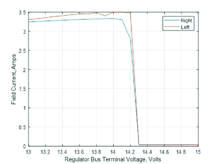
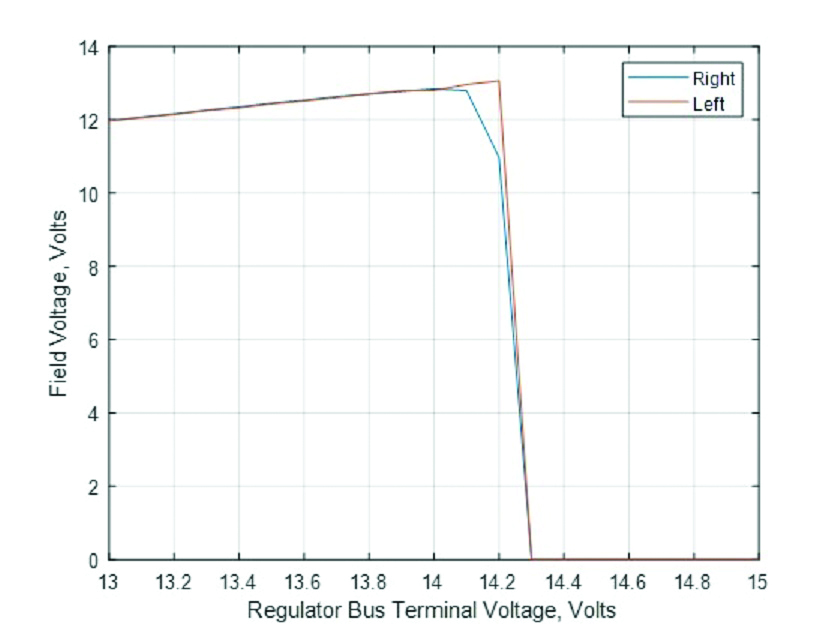
The patent, assigned to Raymond L. Meisenheimer of Cherry Hill, New Jersey, provided a correct schematic as well as an extensive design rationale and details of proper operation. Given this information, it was a snap to hook up both regulators to a curve tracer and confirm proper operation as shown in the following charts. As you would expect, when the bus voltage falls below the set point, the regulator maxes out the voltage and current applied to the alternator field winding through the brushes in an effort to raise the bus voltage. Then, as the bus voltage rises and achieves the set point, the regulator throttles back the field voltage and current to hold exactly at the set point. As you can see from the chart, both of my regulators were at some point set to 14.2 volts.
A Master of Design
But Meisenheimer’s design doesn’t stop there. It provides a paralleling connection between the regulators that works as follows. The regulator delivering the higher field voltage “masters” the system and pushes the waterfall curve of the other alternator to the right. In so doing, both regulators now deliver exactly the same field voltage to their attached alternator. And if you assume that both alternators have identical winding resistance and current gain — usually about 5 ohms and 25x current gain at cruise rpm — then when running closed loop, both alternators deliver exactly the same current onto the bus, regardless of load.
So what if one regulator fails to produce output? The surviving regulator operates independently and at its set voltage, with no ill effect, since it’s connected to the other regulator through a diode. How about if one of the output power transistors fails as a dead short, now feeding bus maximum on the control line to the other regulator and driving both alternators to maximum output regardless of load? Meisenheimer obviously thought of this scenario, too, and that’s why each regulator has an independent overvoltage relay connected in series, set to trip at 16.5 volts. Any guess as to who holds the patent on the overvoltage relay?
The Name Rings a Bell
This clever circuit design was obviously the product of an experienced hand, and coupled with the Cherry Hill address, made me increasingly curious as to who Meisenheimer was. A quick search of the patent database provided some additional information. Meisenheimer had been with RCA corporate research (David Sarnoff Labs) for nearly 30 years, culminating in a position as chief engineer. Between the early ’40s and the late ’60s, he was issued dozens of patents covering virtually all aspects of television design, most as the single inventor. On all the patents, he signed the inventor line as “Raymond Lamar Meisenheimer.” Lamar. That name is familiar, I thought. But why?
The answer came to me one morning at the airport. My neighbor and I were chatting while he changed the oil in his late-model Skylane. As we talked, I noticed the regulator mounted to the firewall and its logo: Lamar Corporation, Cherry Hill, NJ. Looking around the engine compartment, I saw that many components were made by Lamar. That’s when it sunk in. Meisenheimer is the father of GA starting and charging systems, and his products and inventions appear in the vast majority of our fleet. Wow, just wow!


