
Before we begin, we need to define what the visual segment of an instrument approach is: It is the segment between the decision altitude and the runway threshold.
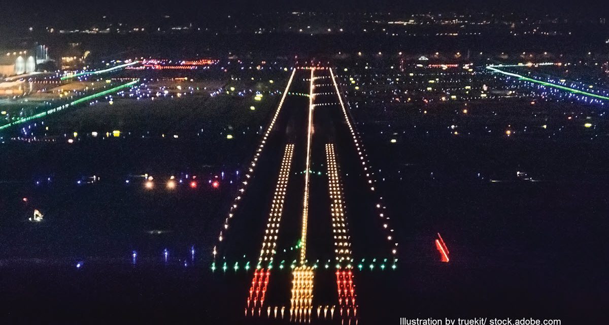
By definition, this part of an instrument approach is flown in visual conditions. However, on some approaches, when the visual segment is flown at night or in low visibility conditions, a hidden danger lurks. That danger is the possibility of a controlled flight into the terrain even though one is perfectly centered on the glideslope or glidepath.
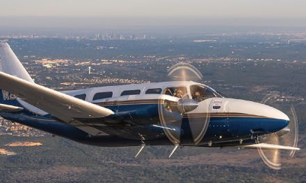
Pilots should understand that flying an ILS glideslope, or an LPV/VNAV glidepath in the visual segment to the runway does not guarantee obstacle clearance. I learned this from personal experience one dark and foggy night in 2017.
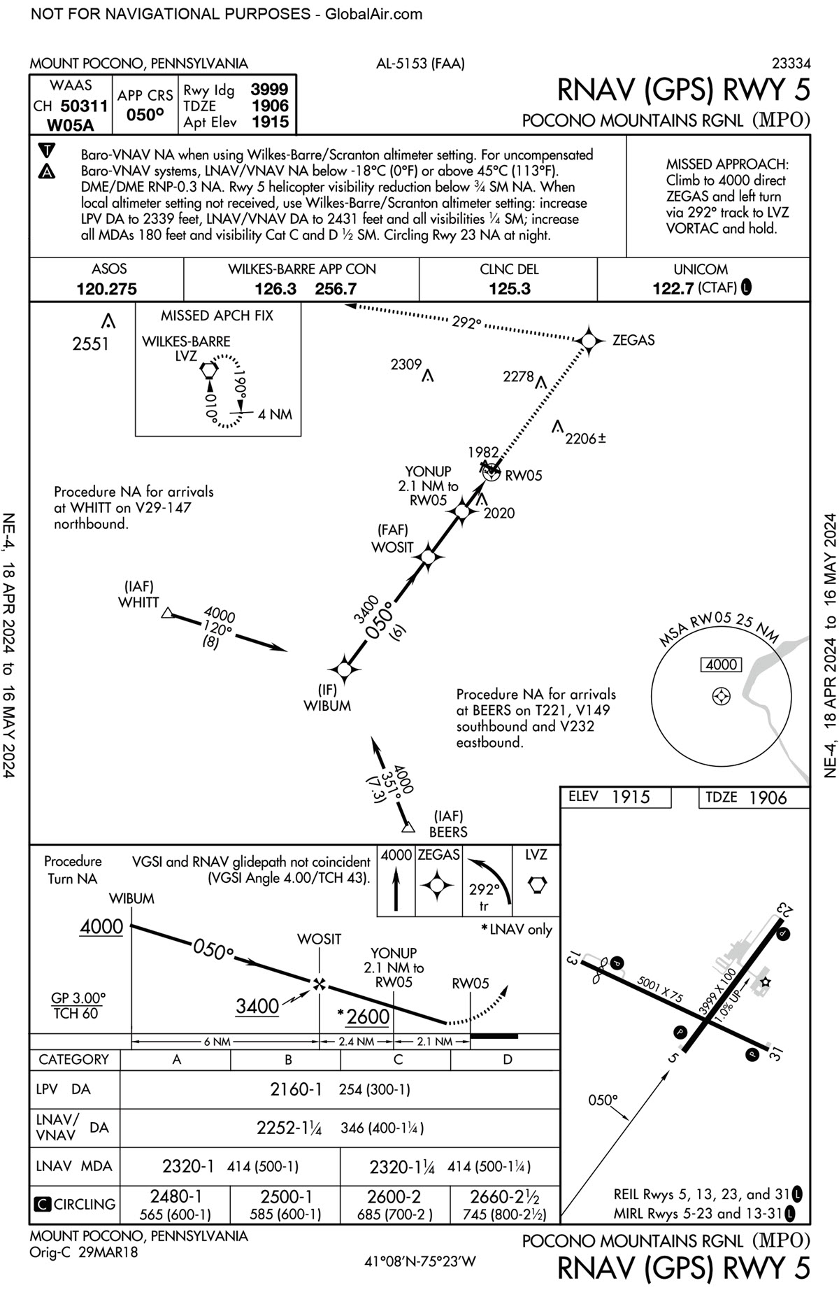
I was flying my Pilatus PC-12NG on the RNAV LPV approach to Runway 5 at my home airport of Mount Pocono, PA, KMPO. While descending on the LPV glidepath at night where the ceiling was near approach minimums, I broke out of the weather just prior to the decision altitude. With the glidepath indicator perfectly centered, I looked up to fly to the runway visually.
The first thing I noticed was that the PAPI lights were both red! This meant that while I was perfectly on the approach glidepath, I was well below the visual glidepath! Something did not compute.
At that point I leveled off until the PAPI lights were white and red, then descended safely on the Visual Glide Slope Indicator, or VGSI, to the runway. After this incident, I began to investigate why there was a discrepancy between a published glidepath and a visual glidepath, and what I found was startling!
I had always assumed that a glideslope or path would guarantee obstacle clearance in the visual segment from minimums to the runway. But I recently discovered my assumption was not always true.
The mystery was solved when I saw on the RNAV RWY 5 approach chart the words “VGSI and RNAV glidepath not coincident (VGSI Angle 4 Degrees/TCH 43)”. In plain language, that means that following the 4-degree PAPI visual descent angle will result in crossing the runway threshold (TCH) at 43 feet.

Almost all ILS glideslopes and LPV/VNAV glidepaths are set at a 3-degree descent angle, and some are even less than 3 degrees. This is to allow for a shallow and more stabilized approach. Both are also designed to guarantee obstacle clearance when flown properly. However, that guarantee ends at the decision altitude.
Below approach minimums, most, but not all, glideslopes and glidepaths do NOT assure obstacle clearance if flown to the runway threshold. And here is why that is true.
In the example above, the RNAV RWY 5 glidepath is set for a 3-degree descent from the final approach fix to the decision altitude. But there are obstacles in the visual segment between decision altitude and the runway threshold that require a 4-degree descent angle to clear them. Continuing the LPV glidepath in low visibility, and especially at night, might result in colliding with the trees off the end of the runway.
On approaches like these, the safest technique is to level off momentarily at or before decision altitude until intercepting the PAPI, then fly it to the runway. Refer to the IAP chart vertical profile.
THE BAD NEWS
On Page 731, chapter 5-4-5 of the 2024 AIM, it states the following;
“There is no implicit obstacle protection from the MDA/DA to the touchdown point. Accordingly, it is the responsibility of the pilot to visually acquire and avoid obstacles below the MDA/DA during transition to landing.”
Because of this, the visual glidepath (PAPI or VASI) always has precedence over a published glidepath or glideslope below approach minimums. Flying the published glidepath or glideslope below minimums may result in a CFIT type of accident. And getting a dot or more low on the glidepath increases the chances of a CFIT type of accident.
THE GOOD NEWS
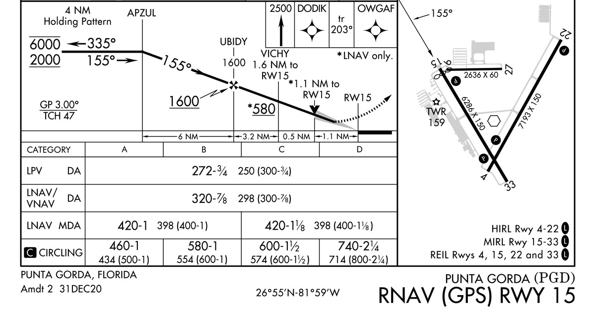
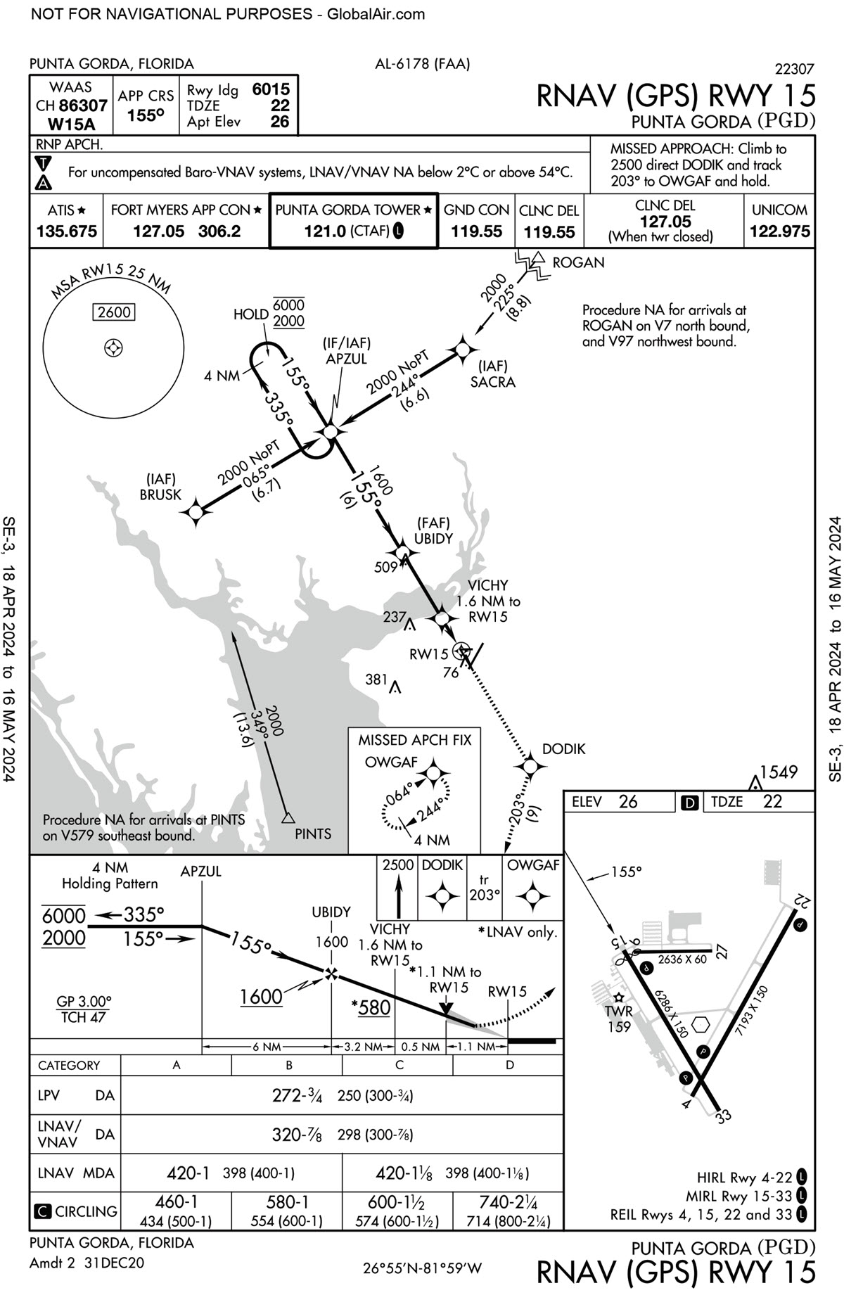
Some instrument approach charts have a symbol that tells the pilot that he or she can safely fly the published glideslope or glidepath obstacle free in the visual segment from decision altitude to the runway.
Above is an example of an instrument approach where the pilot can safely fly the glidepath to the runway in the visual segment. Note the very subtle light gray shadow extending from the VDP/DA to the runway threshold in the vertical profile window on the chart below. Why the FAA did not make this symbol more apparent is a mystery.
CONCLUSION
The information in this tutorial should motivate instrument pilots to study their approach charts with a critical eye prior to boarding their airplane. This allows for discovery of the fine details and small print on the chart without the distraction of flying an airplane.


